|
I'm working on a subsystem which will allow my 6.5"
coil to run reliably in a DC mode of operation ( i.e. primary capacitor is charged using
high voltage DC instead of AC). I'd eventually like to incorporate these findings into the
design of a large coil. Following is a log of my progress.

 | The first steps were taken in the Spring of 2000 when I had a number of
discussions with Kevin Ottalini (one of the
Tesla Coil DC guru's). I also received input directly and indirectly from Ross Overstreet, Jim Lux, and Jeff
Parisse.
|
| First thing I needed was to build a DC Bridge Rectifier capable of
handling a minimum of 500ma at 32kv (15kv*1.414*1.5). This resulted in the construction of
two bridges.
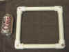
 | Kevin provided me with eight H2612-22's which I configured as a
bridge with two series diodes per leg. This configuration yields 330ma @ 24kv.
|
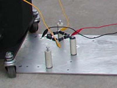
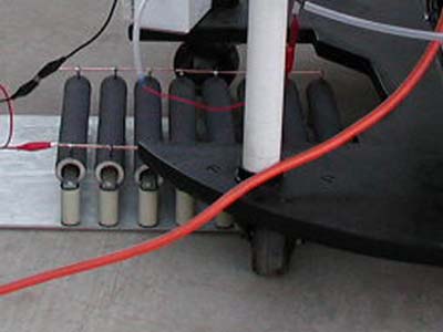
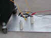
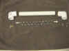
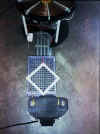
| I also purchased a bag of one hundred 1N5408's (3a @ 1000v). I
used these to build four strings of twenty diodes. Each string fits into a PVC pipe for
insulation and easy replacement. The assembled unit is capable of 3a @ 40kv.
|
|
| The DC discussion evolved into a small get
together at my house in May of 2000. We looked at Kevin's redesigned DC Coil and
talked about various aspects of DC operation. I also purchased a bunch of high power
resistors from Kevin.
|
| To move further I needed to go through all my test equipment and compete
the many partially finished projects. This motivated me to clean up my Tektronix 466
Analog Storage Scope. I also finished the Fiber Probe kit I received from Terry Fritz, and threw together a 15kv DC meter.
|
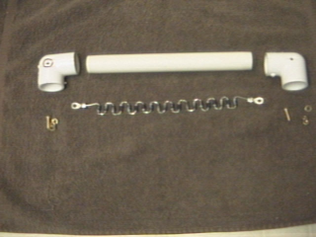
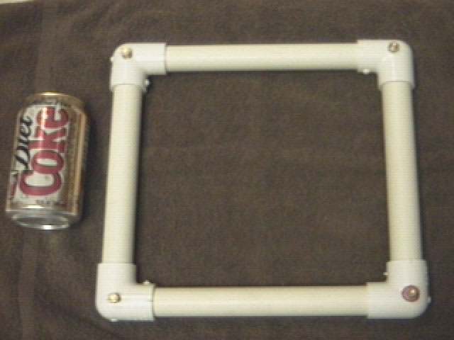
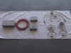
| Kevin suggested using a limiting resistance of 10K to 20k-ohms and
slowly reducing it in steps down to 5k-ohms. Many e-mails later I decided to build a
limiting resistor of 2.5K-ohms @ 1,300w (The "More Power is Better" bug took
over).
|
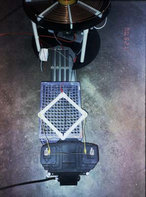
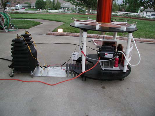
| I put the 3a bridge and 2.5k-ohm resistance in my charging circuit
(between the PT and the RSG). Low power tests at 60% were a great success. Everything ran
very smoothly (without the need for any ballasting) and measurements on the running coil
were comprehendible. Break rates from 240pps down to 1pps were obtained by letting the RSG
spin down while the coil ran.
|
| Ross came over on the 5th of August, 2000 and helped me document,
measure, and then test the current set-up at full power.
|
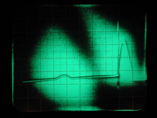
| Full Power Runs, Results, and Consequences -
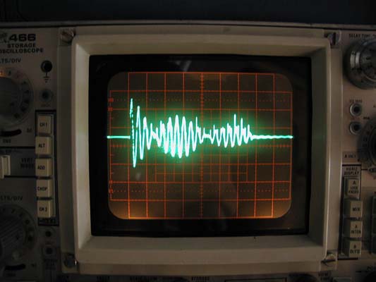
| We were able to see the energy transfer and third notch quenching while
looking at the primary current. |
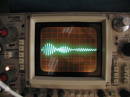
| We saw the ring-up while viewing the secondary voltage. |
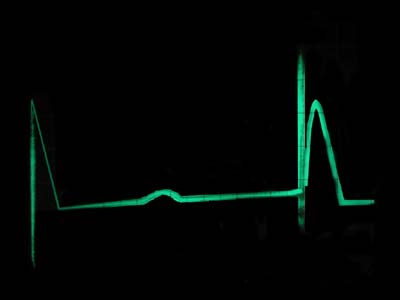
| Monitoring charge current we were able to see that the caps were reaching
full charge (at the reduced voltage we were using) before the next 240bps bang. |
| The first high power DC runs were with the H2612-22 diode bridge.
Performance was about the same as using AC. |
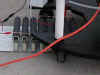
| The primary cable running to the tap, which I had temporally re-routed,
took a direct strike blowing the bridge. Arcs stopped and the input current went sky high. |
| Replaced the bridge with the one made of 80 1N5408's and performance was
back to where it should be. |
| We plugged the PT into a 20-amp variac and ran the coil again. I was able
to get the same performance from the 20lb variac as with my 400lb controller. |
| We got out my 2100w generator and plugged the small variac into it. The
coil ran but the generator was struggling with the rapidly varying load and the current
requirement was at the generators maximum. |
| After a bit of runtime on the generator the second bridge blew without
warning. |
| There was never any indication of heating in either bridge. |
| The resistors barely got warm enough to sense (with a calibrated finger).
|
| I probably went way too low on the resistance 2.5k-ohms and should I bump
it up to 5K or more next time. |
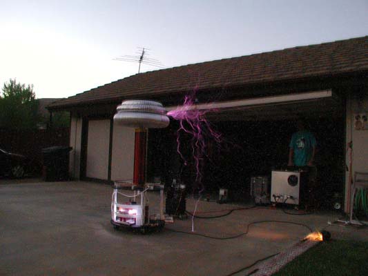
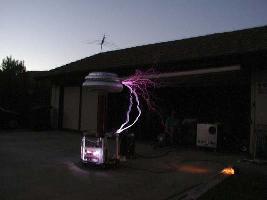
| Since we were out of DC parts we switched back to A/C and took a bunch
(75) pictures with Ross' new camera. |
|
| Benefits of DC (as I currently see them) -
| DC eliminates the need for current limiting/ballasting on the low voltage
side of the PT/Pig. |
| Break rates can be varied from 1pps up to 700+ bps creating different
effects. |
| Measurements are easier and more accurate. |
| Bang size is predictable and reproducible. |
| Easily converted to A/C operation. |
|
| Drawbacks of DC (as I currently see them) -
| More points of failure. In particular the bridge rectifier as the
resistor bank is unlikely to fail. |
| Reliability of the bridge (Further testing and adjustment of the
resistance may make them more robust). |
|
| Failure Analysis -
| Looks to me like I over did the max forward current.
15,000volts/2,500ohms=6amps My 1N5408 bridge should have been able to handle 3a@40kv and
the H2412-22 bridge 600mA@24kv. |
| All legs tested OK at 120v and the signal looked the same as with good
diodes. So much for my testing procedure using a 40w 120v bulb in series with the diode in
question. |
| Measuring the resistance though told a different story. Each bridge had
one bad leg (one was on the positive side and one was on the negative side). |
| The twenty 1N5408 diodes in the bad leg measured 10M-ohm in either
direction. A good diode measures 10M one way and 300M-400M the other way. |
| The two H2612-22 diodes measured different. One was 10M-ohm in both
directions and the other one was 14M one way and 25M the other way. |
|
| Next Step -
| The next step is to fix the bridges, increase the limiting resistance to
5K-ohms, then re run the full power tests. |
| It would also be useful to capture the charging current on the scope
while performing the tests above. |
| Investigate ways of hardening the bridge including adding filters. |
|
|